
.png?width=49&height=23&name=HIMA%20Logo_mini%20(1).png)
In Functional Safety, safety instrumented functions (SIF) implemented in safety instrumented systems (SIS) must ensure a certain level of risk reduction. The measure of the performance required from these SIFs is referred to as safety integrity level (SIL) (see Figure 1). The IEC 61508 standard defines four SILs, with SIL 1 being the least and SIL 4 the most dependable. Which SIL should be applied depends on a combination of various quantitative and qualitative factors, including risk assessments and safety lifecycle management. However, other standards may have different SIL definitions. In such standards, we can find tables with a SIL quantification based on the probability of failure of a given SIF.
In this context, several members of the Functional Safety community, especially beginners in this area, believe that the SIL of a SIF is mainly determined by a quantitative analysis that is largely reduced to the calculation of the probability of failure. However, this is definitively a false assumption. For instance, the IEC 61508 standard introduces a set of requirements that employ both qualitative and quantitative constraints in order to determine the safety integrity level of a SIF. These requirements can be categorized into three main constraint types: systematic capability constraints, architectural constraints, and probabilistic performance metric constraints (see Figure 2).These constraints can be expressed by three essential safety parameters: the safe failure fraction (SFF), the hardware fault tolerance (HFT) and the probability of failure on demand (PFD). Here, the individual parts of a SIF, e.g. sensors, the logic solver and final elements that work together to implement the individual safety loops, must comply with these constraints of the required SIL. This means that all components within that loop must meet an SFF, HFT and PFD requirement for the intended SIL.
In this module, we focus on the architectural constraints that define the structures of safety systems and highlight the various system architectures used to enhance the dependability of these systems. However, due to the complexity of the topic and the dependence with other constraints, we first introduce a set of definitions of essential terms in this context. Afterwards, we briefly describe the general structure of a SIS and a SIF, finishing with an overview of the most essential safety architectures.

Figure 1: SIS, SIF and SIL
Source: HIMA Paul Hildebrandt GmbH
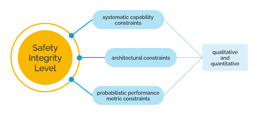
Figure 2: Safety constraints classification
Source: HIMA Paul Hildebrandt GmbH
Table of Content
1 Terminology for the structure of safety systems
1.7 Safety system and safety function
1 Terminology for the structure of safety systems
According to the IEC 61508 standard, a safety-related system can consist of subsystems and elements. On a lower level, further terms such as parts and components are also used. In addition, a safety-related system can be divided into a channel or a group. However, these terms are not used consistently in standards and the literature. For this reason, we provide a common terminology definition based on the IEC 61508 standard and apply this definition throughout the module.
1.1 System
The term system is not defined as a single term in the IEC 61508 standard. In general, it describes the overall top level of a safety-related architectural design.
1.2 Subsystem
The IEC 61508 standard describes a subsystem as an entity of the top-level architectural design of a safety-related system where a dangerous failure of the subsystem according to Section 3.6.7 (a) in IEC 61508 results in dangerous failure of a safety function according to Section 3.6.7 (a) in IEC 61508.
Example
The sensor part (e.g., multiple sensors), control unit and actor component (e.g., final elements) of a safety system are very good examples of a subsystem.
1.3 Element
According to the IEC 61508 standard, an element is a part of a subsystem, a single component or any group of components that performs one or more safety functions. An element may contain hardware and/or software.
Example
The IEC 61508 standard introduces a sensor, a programmable controller or a final element as typical elements.
1.4 Component
The term component is not defined in the standard IEC 61508. However, it is often used in the standards to describe the lowest level of a safety-related architectural design. A component is a part of an element.
Example
RAM memory can be a component of a microcontroller, which is considered an element.
In addition to the term component, standards use the terms part, item, unit, functional unit and others, which will not be focused on this module.
1.5 Channel
A channel represents an element or a group of elements that independently implement an element safety function.
Example
A two-channel configuration is one with two channels that independently perform the same function.
A channel can be used to describe a complete system or a portion of a system (for example, sensors or final elements).
1.6 Group
A group consists of multiple channels on the same subsystem.
Figure 3 shows an example that describes a possible use case of the terminology introduced above.
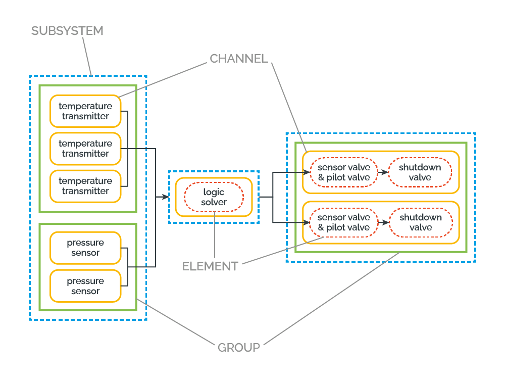
Figure 3: Terminology
Source: HIMA Paul Hildebrandt GmbH
1.7 Safety system and safety function
Based on the basic term definitions above, the overall definition of safety systems and safety functions can be formulated as follows:
- In the field of process industry, the term safety instrumented system (SIS) is used as a synonym for an E/E/PE safety-related system. The IEC 61508 standard itself does not use the term SIS, but rather the term E/E/PE safety-related system or its short form safety-related system. However, this term defines the same concept and uses a language that can be broadly applied to many industries. Therefore, the term SIS will also be used in this module as a synonym for safety-related system to refer to a system that implements one or more safety instrumented functions (SIFs) using E/E/PE in combination with other active (e.g., mechanical) technologies. The main function of a SIS is to protect another system, usually the equipment under control (EUC).
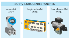
- The term safety instrumented function (SIF) refers to a safety function that is performed by a SIS. The main structure of a SIF usually resembles the structure depicted in Figure 4 and can be described as follows:
-
- Sensor subsystem (S) to monitor some process parameter or the presence of a command.
- Logic solver subsystem (LS) to decide if it is necessary to act upon the monitored signals.
- Final element or actuating elements subsystem (FE) to carry out the necessary tasks it decided to perform.
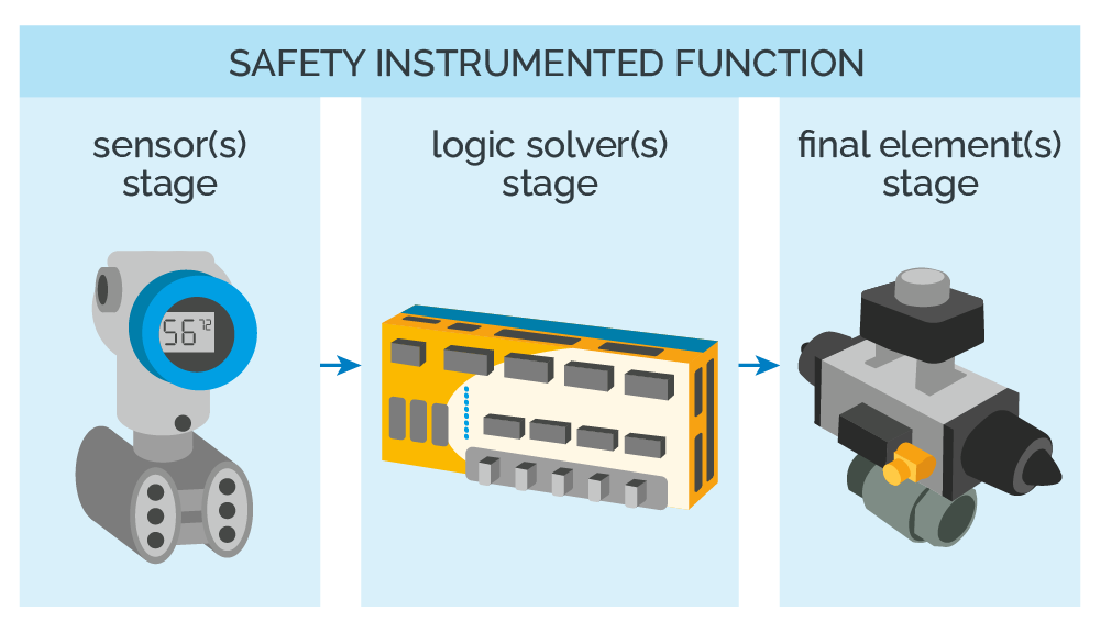
Figure 4: Structure of a safety instrumented function
Source: HIMA Paul Hildebrandt GmbH
Based on the introduction above, the relationship between a SIF and SIS can be summarized as follows:
- A SIF generally consists of sensor elements, a logic solver element and final elements.
- A SIF monitors a process, determines if the process is operating within specified acceptable limits and intervenes appropriately if the process strays outside its acceptable limits.
- A SIF itself is subject to failure and can fail in one of two ways:
- First, it can erroneously determine that a correctly operating process is outside its acceptable limits and inappropriately intervene in the process operation. This is called a safe failure of the SIF.
- The second way in which the SIF can fail is that can be incapable of determining if the process is within acceptable limits and/or be therefore incapable of appropriately intervening when the process strays outside its acceptable limits. This is called a dangerous failure of the SIF.
- Safe failures that are detected by diagnostic measures are called safe detected failures. If these failures are not detected, they are usually called undetected safe failures.
- Dangerous failures that are detected by diagnostic measures are called dangerous detected failures. Dangerous failures that are not detected by diagnostics are called dangerous undetected failures. These failures are relevant as a basis for evaluating safety-related systems. Statistically, this final element makes up 50% or more of the dangerous undetected failures in a SIF, as shown in Figure 5.
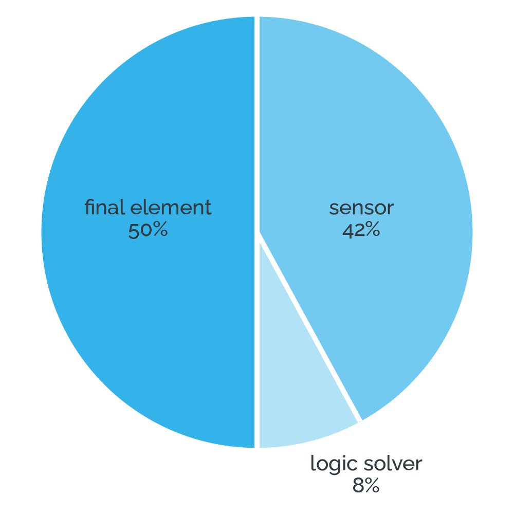
Figure 5: Failure ratio in a SIF
Source: HIMA Paul Hildebrandt GmbH
Example
As a simple example, a process application SIS is a system consisting of a PLC subsystem (logic solver), a pressure transmitter subsystem (sensor) and a valve subsystem (final element). The pressure transmitter subsystem takes measurements and reports them to the PLC subsystem, which analyzes these measurements, evaluates them and decides whether to trigger the final element to close the valve. The final element subsystem is typically in low demand. Thus, it remains in one position for most of its installed life until activated to perform its SIF. For instance, the valve subsystem is in contact with the process fluid, making it susceptible to deposition and corrosion, and potentially unable to respond to a demand. This underlines the importance of not only properly testing the final element to ensure operation but also making the proper sizing, selection and engineering critical to meeting the safety function.
1.8 Safe failure fraction
Another relevant term for evaluating safety-related systems is the safe failure fraction (SFF), which is the percentage of a system’s safe failures compared to its total failures. To calculate an SFF of the subsystem, it is first necessary to quantify the random hardware failures that can occur within a SIS and how they can affect the overall safety of this element or subsystem.
As introduced above, they can be categorized into one of four types: safe undetected (SU), safe detected (SD), dangerous detected (DD), and dangerous undetected (DU) (see Figure 6).
- Safe failures, either detected or undetected, are failures that do not affect the safety function of the system.
- Dangerous failures pose a significant safety risk and can potentially have catastrophic consequences. If a SIS fails but the failure is detected and reported by the diagnostic functions, the system is brought to a safe state and classified as DD. Even if a device has a large fraction of dangerous failures, as long as enough of these can be detected and safe action can be taken, it is still considered a safe device. However, if such a failure occurs without being detected and reported, this can create a critical state and is therefore categorized as DU.
The SFF is calculated according to the following formula:
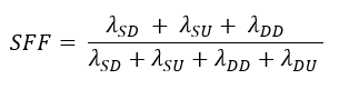
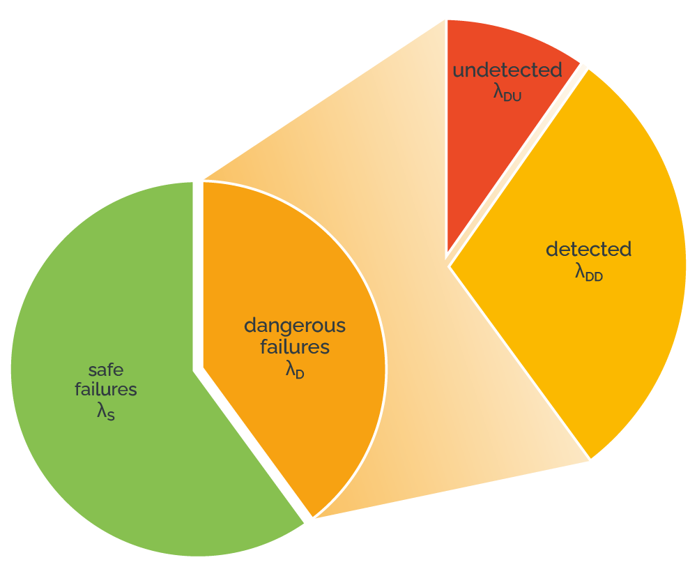
Figure 6: Failure classification in a SIF
Source: HIMA Paul Hildebrandt GmbH
2 Architectural constraints
Architectural constraints refer to the minimum hardware fault tolerance (HFT) required to attain a particular SIL. HFT is the ability to tolerate faults. In more detail, it is the ability of a subsystem to continue to perform a required function in the presence of hardware faults or errors. It is defined by the number of redundant devices in a SIF element that can fail and have that SIF element remain functional. However, HFT is not a synonym for redundancy. HFT is based on using redundant channels to be able to claim a particular SIL. For this reason, several system architectures are used and will be defined in the following sections.
An additional essential architectural constraint is the diagnostic coverage (DC). DC is a measure of a system’s ability to detect failures. This is a ratio between the failure rates for detected failures to the failure rate for all failures in the system.
3 MooN architectures
As mentioned above, a SIF structure can be arranged in several configurations in order to achieve various reliability, safety and availability goals. These various arrangements of control system components are referred to as system architectures. The common system architectures rely on redundancy and diagnostics. Redundancy means the presence of more than one element to carry out the same function. Redundancy provides fault tolerance and increases the reliability. On the other hand, it adds complexity that must be balanced against the benefits. Redundancy may be classified as active or passive (standby) redundancy. It can be realized in hardware or software, partially or fully. Diagnostics are measures and mechanisms to detect failures in systems.
In the literature and standards, these system architectures are commonly known as MooN architectures. For example, in a SIF with three subsystems, each subsystem can have a different architecture. When we talk about a MooN architecture (M out of N), we have:
- N channels (e.g., N sensors, N shut-off valves, N microprocessors in the PLC, N transistors in each PLC digital output, etc.).
- There is a channel voting system (N channels) so that M channels must act for the architecture to perform its safety function correctly (e.g., if there are 2 sensors with a 1oo2 architecture, then it is sufficient to exceed the trip setpoint in 1 channel for the SIF to act on the final element).
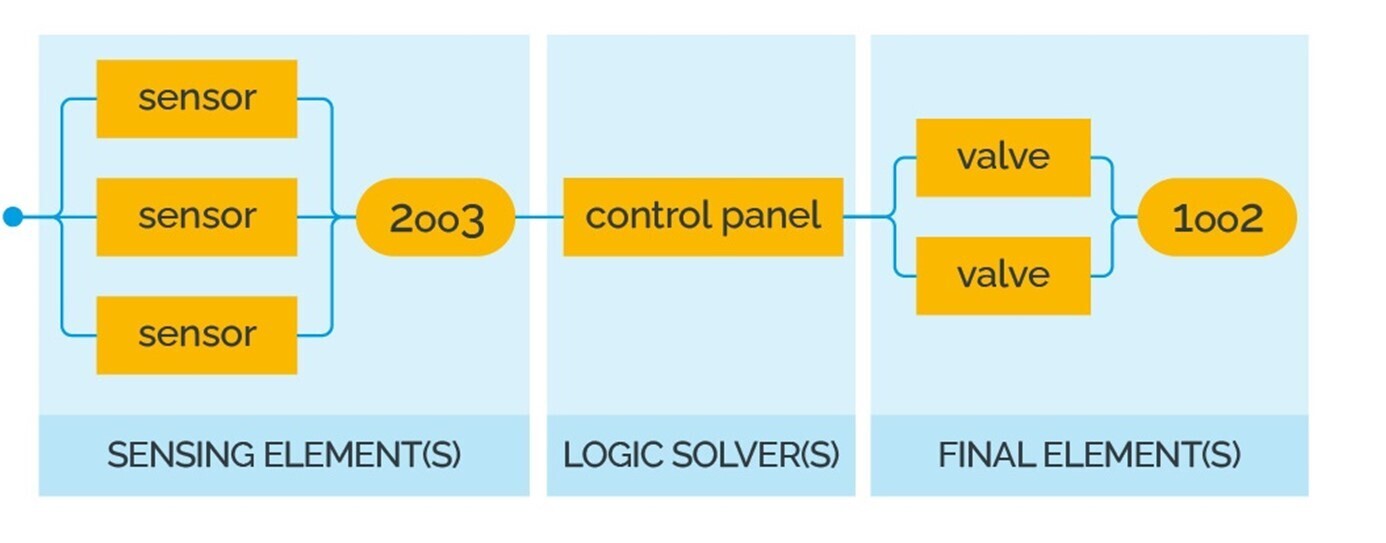
Figure 7: Example of the use of MooN architectures in a SIF
Source: HIMA Paul Hildebrandt GmbH
The following sections will introduce common system architectures in accordance with the IEC 61508 standard. It is important to mention that the various standards, experts and industry may have slightly different definitions for some architectures, depending on the use case of the architectures. In this module, the definitions rely on the IEC 61508 standard, edition 2.
3.1 1oo1 architectures
The 1oo1 architecture represents a minimum system. It involves a single channel and is normally designed for low-level safety applications. When the safety function is requested, this one channel must execute it correctly and bring the system into a safe state. If a dangerous error occurs in the channel, this will immediately result in the loss of safety function. The 1oo1 architecture has no fault tolerance. Therefore, this system is assigned an HFT = 0.
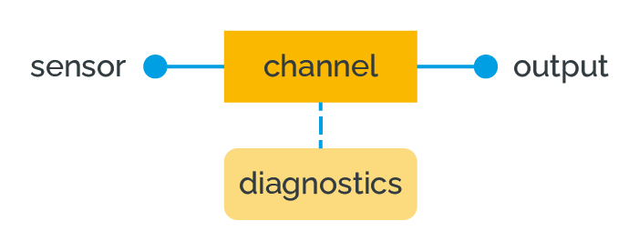
Figure 8: Block diagram of a 1oo1 architecture
Source: HIMA Paul Hildebrandt GmbH
3.2 1oo1D architectures
Figure 9 shows an architecture that uses a single controller channel with diagnostic capability and a second diagnostic channel wired in series to utilize the diagnostic signal to de-energize theoutput. This differs from the 1oo1 only in that the switch is wired in series with the output to de-energize the output on a diagnostic fault. This system represents an enhancement used for safety applications. Diagnostics allow a detected dangerous failure to be converted into a safe failure. In general, additional failure rates must be included in quantitative analysis to account for the extra diagnostic channel. In systems using external diagnostic control devices (e.g., watchdog timers), additional failure rates for these external devices must be added to the single-board rates.
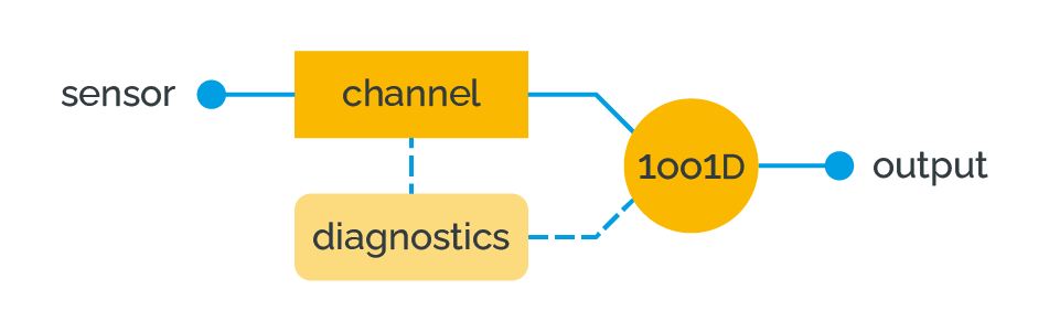
Figure 9: Block diagram of a 1oo1D architecture
Source: HIMA Paul Hildebrandt GmbH
3.3 1oo2 architectures
This architecture consists of two channels connected in parallel such that either channel can process the safety function (Figure 10). Thus, there would have to be a dangerous failure in both channels before a safety function fails on demand. It is assumed that any diagnostic testing would only report the faults found and would not change any output states or change the output voting.
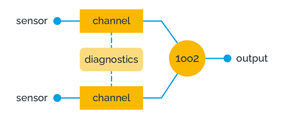
Figure 10: Block diagram of the 1oo2 architecture
Source: HIMA Paul Hildebrandt GmbH
For de-energize-to-trip systems, which means that the final element will enter its safe state when power is removed, a series connection of two output circuits requires that both controllers of a 1oo2 architecture fail in a dangerous manner in order for the system to fail dangerously (Figure 11).
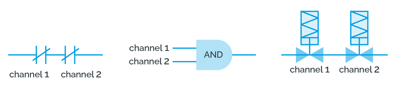
Figure 11: The 1oo2 architecture as a serial connecti
Source: HIMA Paul Hildebrandt GmbH
3.4 1oo2D architectures
This architecture consists of two channels connected in parallel (Figure 12). During normal operation, both channels need to demand the safety function before it can take place. In addition, if the diagnostic tests in either channel detect a fault, the output voting is adapted so that the overall output state then follows that given by the other channel. If the diagnostic tests find faults in both channels or a discrepancy that cannot be allocated to either channel, then the output enters the safe state. In order to detect a discrepancy between the channels, either channel can determine the state of the other channel via a means independent of the other channel. The channel comparison / switch-over mechanism may not be completely efficient therefore K represents the efficiency of this inter-channel comparison/switch mechanism, i.e., the output may remain on the 2oo2 voting even with one channel detected as faulty.
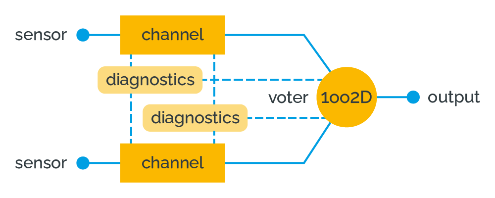
Figure 12: Block diagram of the 1oo2D architecture
Source: HIMA Paul Hildebrandt GmbH
3.5 2oo2 architectures
This architecture consists of two channels connected in parallel so that both channels need to demand the safety function before it can take place. It is assumed that any diagnostic testing would only report the faults found and would not change any output states or change the output voting.
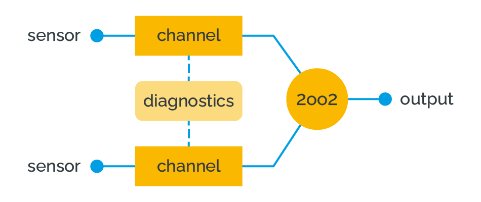
Figure 13: Block diagram of the 2oo2 architecture
Source: HIMA Paul Hildebrandt GmbH
As we can see, the simplified block diagram of the 2oo2 architecture (Figure 13) is identical with the block diagram of the 1oo2 architecture (Figure 10). However, the execution of the outputs is significantly different. For a 2oo2 architecture, the outputs of two controllers are wired in parallel. To trigger the safe state, both controllers need to demand the safe state. In other words, if one controller fails, the other is still capable of performing normal operation.
4 Comparison and evaluation
In this section, we introduce the evaluation of the architectural constraints according to the IEC 61508 standard from our point of view. It is important to mention that this evaluation should usually be done on an individual element or subsystem basis. Therefore, we take and analyze the example of a subsystem, e.g., a logic solver.
Architectural constraints are usually defined upon the design of the logic solver. When using a COTS (commercial off-the-shelf) safety logic solver, a manufacturer normally provides a safety manual that describes the architectural constraints and states information about the redundancy and the effects of the redundant channels on the safety of the availability of the logic solver.
Based on the architectures presented above, the redundant channels can simply help to enhance the safety of the availability of a subsystem. To keep the evaluation simple, we focus on subsystems with the dual channels to discuss the various configurations. However, the carried analysis can be applied to any other type of redundancy.
As mentioned above, the following architectures may be applied with dual channels: 1oo2, 2oo2 or 1oo2D.
In a logic solver with a 2oo2 safety architecture, the safety function performed by this element will be triggered only if both channels trigger the safe state. In this case, we can state that the HFT is equal to 0, even if redundant channels are used.
If the logic solver is realized with a 1oo2 safety architecture, the safety function performed by the subsystem is triggered if any of the two channels will trigger it. Therefore, the HFT is equal to 1 in this case, even if the same amount of redundancy is used.
A subsystem with a 1oo2D safety architecture is used in different contexts, which could be misleading. At first glance, it seems to be similar to the 1oo2 architecture, but with more sophisticated diagnostic functions. Some literature and safety system manufacturers are using it in this context. However, according to the IEC 61508 standard the 1oo2D architecture has more similarity to the 2oo2 architecture. To understand this, we can take a deeper look at its behavior.
- Under normal operating conditions, both channels need to demand the safety function before it can take place, as per a 2oo2 architecture.
- If a fault in a channel is detected, then the faulty channel is excluded from voting. In this case, we switch to 1oo1 architecture.
- If a fault of both channels is detected or if there is a discrepancy between channels that cannot be allocated to either channel, then the system goes to the safe state.
- In this case, in normal operating conditions, the architecture is 2oo2, and the change from 2oo2 to 1oo1 is performed as a result of the diagnostics.
In other cases, the architecture corresponds to a cold redundancy, where the channels are divided in a main channel and a redundant channel. The redundant channel only takes the command, if the diagnostics unit detects a fault in the main channel. In other words, in normal operating conditions only the main channel performs the safety function, and the change to the redundant channel is performed as a result of the diagnostics.
While the quantification of HFT for the 1oo2 and 2oo2 architecture is simple, this classification can be tricky for the 1oo2D architecture. In fact, various experts and literature references classify the 1oo2D architecture as a HFT=1 architecture, while others define it as a HFT=0 architecture.
To clarify this, we try to understand the point of view in the standard IEC 61508. In part 2 of the standard the term HFT is defined in Section 7.4.4.1.1 as follows:
- A hardware fault tolerance of N means that N+1 is the minimum number of faults that could cause a loss of the safety function.
- In determining the hardware fault tolerance, no account shall be taken of other measures that may control the effects of faults such as diagnostics.
- The hardware fault tolerance requirements apply to the subsystem architecture that is used under normal operating conditions.
Based on this definition and the definition of the 1oo2D architecture above, we aim to define it as HFT=0 because:
- During normal operation, both channels need to demand the safety function in order for it to be performed. This means, the first fault causes the loss of the safety function and HFT=0 (same definition as 2oo2).
- If the diagnostic tests detect a fault in either channel, the output voting is adapted so that the overall output state will follow that given by the other channel. This means that the safety function is performed by a single channel and HFT=0 (1oo1).
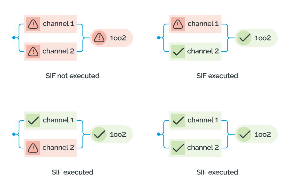
Figure 14: Operation modes of the 1oo2 architecture
Source: HIMA Paul Hildebrandt GmbH
In conclusion, the following implications can be drawn for dealing with the architectural constraints and the architectures used for safety systems:
- The correct architecture of a subsystem shall be clarified in order to evaluate the HFT correctly.
- The HFT is only related to the architectural constraints, and the effects of diagnostics shall not be considered for the evaluation of HFT.
- The architectures can be used either for safety or for availability. In this context, a misleading use of the HFT can occur. Therefore, some literature defines two HFT parameters: HFT (S) for safety and HFT (A) for availability. In this evaluation, which is based on the IEC 61508, only one HFT term is used. Additionally, Figure 15 clearly shows the difference between the architectures used to enhance safety and those used to enhance availability.
- HFT is equal to 1 in a two-channel configuration only if the 1oo2 architecture is in accordance with the IEC 61508 standard, i.e., it includes two channels that can perform the safety function independently from each other and a single fault, even when not detected, does not compromise the safety function (see Figure 14).
- A 1oo2 architecture provides increased safety, so that failure of one channel does not prevent the shutdown action when it is necessary. However, this architecture does not prevent spurious trips, even worse, the probability of spurious trip is doubled. A spurious trip is an activation of a SIF without the presence of a demand.
- A 2oo2 architecture solves the problem of spurious trips since it requires 2 channels to fail at a time in order to initiate the safe state. However, safety is lower with this architecture than with 1oo2, while availability is higher.
- Based on the analysis in the last section, various SIF safety architectures and their corresponding HFT for availability and safety can be classified as in Figure 15.
If we compare the two simplest system architectures, 1oo1 and 1oo2, we can say that the 1oo2 architecture with two safety channels typically gives a higher level of safety than having a single channel. However, a single-channel architecture with very reliable components and/or a higher level of diagnostic coverage could achieve higher safety. For this reason, a comparison is always relative to a common context. In a further context, the system availability could also be a very essential parameter for several applications. In this case, it could be essential to select a system architecture with the ability to continue processing a given functionality in the presence of a failure.
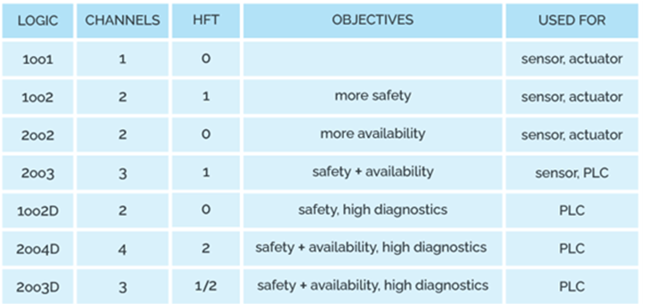
Figure 15: Classification of conventional safety architectures
Source: HIMA Paul Hildebrandt GmbH
As mentioned before, the evaluation based on the dual-channel architecture can be applied on architectures with a higher level of redundancy. For an easier selection of the safety architecture for a proposed system, the various architectures and their safety and availability parameters are shown in Figure 16.
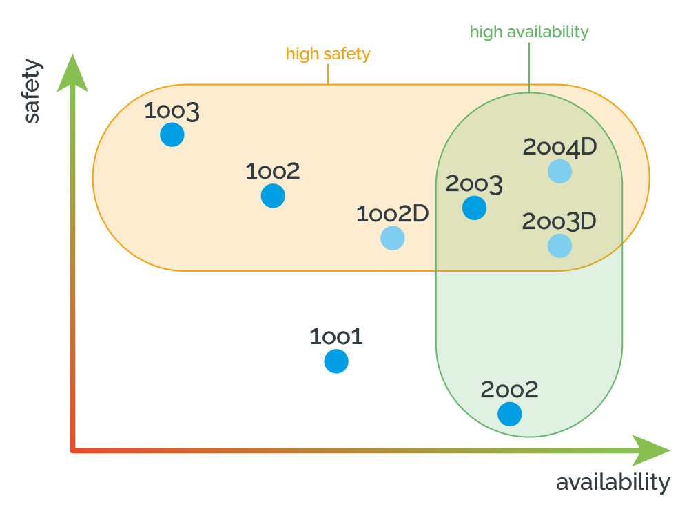
Figure 16: Overview of conventional safety architectures
Source: HIMA Paul Hildebrandt GmbH
Example
In the last section of this module, we give an example of an industrial system to broaden the background introduced in the sections above. The example consists of three major components: a pressure transmitter (sensor), a safety PLC (logic solver) and a valve (final element).
Many major manufacturers provide process transmitters with third-party SIL certifications to provide the industry standard for 4 20 mA output. This analog signal retransmits the process variable to the safety PLC for analysis, where algorithms test to see if the process is within safe operating parameters. If abnormal conditions are determined to exist, an alarm may be sounded; and if dangerous conditions are confirmed, an emergency shutdown sequence may be initiated.
Further exploring the roles of each of these safety system components, all three components must work together correctly in order to allow the process to run in a safe manner or to bring the system into a predictable safe state. The reliability of each component becomes significant to the proper operation of the safety instrumented function, and therefore the safe operation in the plant.
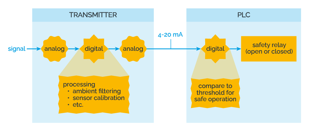
Figure 17: Example of a SIF
Source: HIMA Paul Hildebrandt GmbH
For example, the central component must continuously monitor the process variable and provide this information to the safety PLC via a hardwired connection. What actually occurs, however, is that the analog signal from the sensor is converted to a digital signal for processing. Digital signal processing occurs inside the transmitter electronics to adjust the signal for ambient and process temperature conditions, sensor response errors, signal filtering, user settings, sensor calibration and the process variable display. The resulting conditioned and process signals are converted back to the analog domain to retransmit the 4 20 mA signal over the hardwired connection to the safety PLC. The PLC must now determine if the analog signal reveals a dangerous condition by comparing the level of the analog signal with pre-defined thresholds. Here is what actually occurs. The retransmitted analog 4 20 mA signal must be converted back to the digital domain for processing inside the safety PLC's electronics. The level of the signal is compared to a pre-programmed threshold that is set at the limit of safe operation. If the signal level is determined to be within the safe limits of operation, a relay inside the safety PLC will remain closed. If the signal level is determined to be outside the safe operating limits of the process, the safety relay will open. The safety relay state – whether it is open or closed – will determine what action the final element will take via a hardwired connection.
The final element must now take action to perform the safety function. An example of a final element is a steam cut-off valve to a turbine generator. The valve, or the final element, can quickly close to cut off the steam that passes through the generator’s rotor in order to stop the rotation. Here is what actually happens. A pilot valve is connected to the plant air supply. The pilot valve is actuated by an energizing 120 V AC solenoid coil. When the coil is energized, the valve is held open, allowing plant air to enter the pneumatic actuator for the steam valve. Air pressure is used to hold the steam valve open, allowing steam to enter and cause the turbine generator to rotate. If the signal from the safety PLC opens to de-energize the pilot valve coil, the pilot valve will close, cutting off the air supply to the steam valve, which will cause the steam valve to close. This is an example of a de-energized to trip safety function.
As you can see, there are several components that must operate as designed to shut down the turbine generator in the event of an abnormal condition. Examples of abnormal conditions may include low lubrication oil pressure, high lubrication oil temperature, steam pressure that is too high, inadequate plant air pressure, etc. In order to decrease the safety instrumented function’s probability of failing on-demand, all of the functions described here must work correctly.
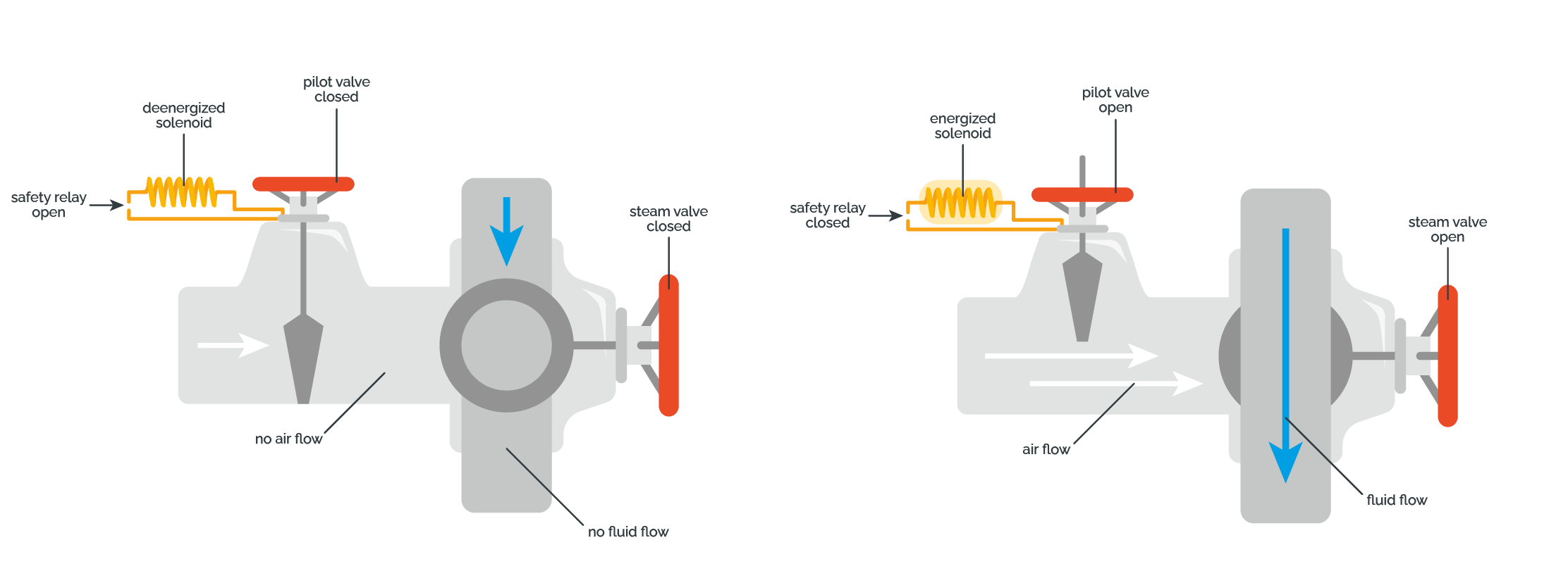
Figure 18: Example of pilot valve: open vs. close
Source: HIMA Paul Hildebrandt GmbH
Conclusion
Functional safety means that one of multiple safety functions will perform the intended function correctly or the system will fail in a predictable safe manner.
A safety instrumented system (SIS) is an implementation of one or more safety instrumented functions (SIF).
A SIS is composed of any combination of sensor(s), logic solver(s), and final element(s), and usually has a number of safety functions with different safety integrity levels (SIL).
The SIL is a quantitative measure for the level of performance needed for a safety function to achieve a tolerable risk for a process hazard. In order to claim a certain SIL for a SIF, the IEC 61508 standard introduces a set of requirements that employ both qualitative and quantitative constraints.
In this module, we introduced the required architectural constraints. In this context, we introduced the terms safe failure fraction and hardware fault tolerance.
In addition, we presented different safety architectures which can be used to extend the safety or availability of a system. The introduced MooN architectures are based on redundancy and diagnostics, and are recommended by the IEC 61508 standard to fulfill architectural constraint requirements. Depending on the implementation of such architectures redundant channels can be used to enhance the safety or availability of a system.
Finally, we gave a general example based on a real scenario to describe how a real safety safety-related system may look like.
Sources
List of References
[1] M. Rausand, Reliability of Safety-Critical Systems: Theory and Applications. 2014. [Online]. Available: https://www.amazon.com/Reliability-Safety-Critical-Systems-Theory-Applications/dp/1118112725
[2] “The role of a sensor, logic solver and final element in a SIS (Safety Instrumented System),” The Ives Equipment Process Engineering & Control Blog. [Online]. Available: https://blog.ivesequipment.com/2017/10/the-role-of-sensor-logic-solver-and.html
List of standards
[1] Functional safety of electrical/electronic/programmable electronic safety-related systems – Part 1: General requirements, IEC 61508-1:2010.